Probe Feature
![]()
This command allows you to measure geometry(ies) using a probe compatible with RDS interface .
Connect the arm, and launch the command. This command is disabled if the arm is not in probe mode.
|
|
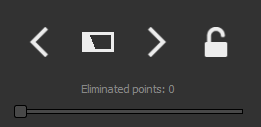
Features are ordered according to the deviation error i.e. the first element in the list is the most relevant feature according to the probed points. If the lock button is active Once the minimum number of points is reached, you can filter the points used for computation by rejecting the worst points with the slider Eliminated points. Information about the current computed feature are displayed in the top left corner of the 3D scene. 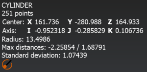
Slider to eliminate points is not available for cones. |
|
|
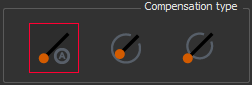
Choose the compensation type:
Not available for planes. |
|
|
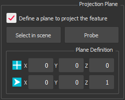
Projection plane section allows you to define a plane to project the measured feature. Select the checkbox Define a plane to project the feature to enable the option. There are three ways to define the plane:
Only available for linear geometries (circle, roundslot and squareslot) If the option Define a plane to project the feature is not enabled while you measure a circle or a slot, the taken plane will be the best plane computed from all the points. |
|
|
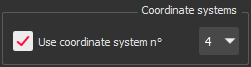
Use coordinate system n° allows you to measure directly in a defined coordinate system. The idea is to make a first measurement and proceed to one or several alignments offline. During these alignments (with the command Geometric Registration, N Points Registration, Best Fit Registration or Axis Registration), you must save or update a coordinate system (from 1 to 9). If no coordinate system has been saved yet, the option is disabled. |
|
|
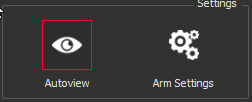
With the Autoview button active Arm settings button opens the settings page Arm Settings. |
|
|
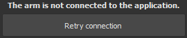
Connection Error If there is an error while connecting the arm, the command will not be displayed, and replaced by this message. Retry connection button will restart the connection. |