Import

images/download/attachments/113546377/CmdImport.svg

This command imports data in the current document.

images/download/attachments/113546377/image2019-7-2_9-6-0.png

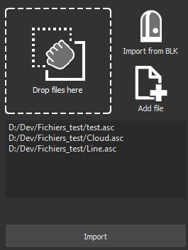
  1. Drag and drop your files in the Drop files here area.

  2. Or click the Import from BLK button to open the Load from BLK command.

  3. Or click the button Add file to choose the files to import.

  4. All the selected files are displayed so that you can delete them if needed.

  5. According to the chosen file format, a second dialog box appears on the right of the first one. It allows you to customize the import. For most of the import formats, you can also choose the unit to use for the import.

  6. Validate with the Import button.

List of available formats:

File format

Information

Options

.asc (Cloud)
.csv
.txt
.xyz
.yxz

  • Reads point clouds or points from an ASCII file

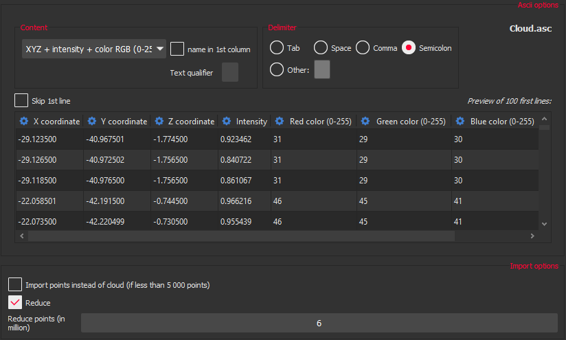
  • Normally the configuration (contents of each column and delimiters) is detected automatically. But you may want to ignore some columns or correct a wrong detection

  • A preview of the file will be shown and you will be able to choose how to read it:

    1. Content: You can define the content of each column of the ASCII file by selecting a predefined configuration in the list. For each configuration you can tell if the first column corresponds to the point's name. You can also quickly change the meaning of each column individually by clicking on column's headers and choosing the right definition on the menu. If the file contains names, you can indicate a text qualifier that will be removed (exemple: if names are written "My Point 1" in file, enter " as text qualifier to have the point named My Point 1 and not "My Point 1").

    2. Delimiter: Define in this part the delimiter used to separate each column

Only 100 first lines of the file will be shown there

images/download/attachments/113546377/image2019-7-2_8-57-4_%281%29.png

.pts
.ptx
.sdb

  • Reads point clouds from a pts or ptx file

  • These formats are mostly used by Leica Geosystems. Scanning directions can be loaded from ptx and sdb format only (refer to Import of clouds \ Scanning direction section above for considerations about scanning direction)

images/download/attachments/113546377/image2019-7-1_12-41-52_%281%29.png

.e57

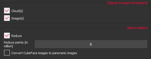
  • Reads point clouds and images from an e57 file

  • You can choose to convert CubeFaces to spherical images at import.

  • The scanning direction can be loaded from this format (refer to Import of clouds \ Scanning direction section below for considerations about scanning direction)

images/download/attachments/113546377/image2019-7-1_12-50-22.png

.3pi

  • Reads point clouds from a 3pi file

  • This format is mostly used by ShapeGrabber. This format is ascii with 5 values: xyzin

    • xyz is the 3D coordinate of the point

    • i. The fourth number "i" is the intensity of light reflected by the model. This value will be low for dark surfaces and high for bright surfaces. Typical values will be between 1200 and 14000

    • n is the point number inside its profile. This value is ignored

  • When this type of cloud is entered, the software automatically sets the inspection representation mode and you can modify this representation mode. You can also modify the inspection color mapping with Edit Colors

  • You can manage 3pi files with transformation by checking the option

images/download/attachments/113546377/image2019-7-1_12-50-58_%281%29.png

.nsd

  • Reads (x, y, z, intensity, R, G, B) points in a file with the native 3DR binary format

  • The scanning direction can be loaded from this format (refer to Import of clouds \ Scanning direction section below for considerations about scanning direction)

.raw

  • Reads (x, y, z) points in a file with the ASCII format

  • X, Y and Z coordinates are one after the other with or without line feed or return

.ac

  • Reads point clouds from a Steinbichler or TScan file

images/download/attachments/113546377/image2019-7-1_12-41-52_%281%29.png

.fls
.fws

  • Reads point clouds from a Faro file

  • Scanning direction can be loaded from these formats (refer to Import of clouds \ Scanning direction section below for considerations about scanning direction)

images/download/attachments/113546377/image2019-7-1_12-41-52_%281%29.png

.las
.laz

  • Reads point clouds from a las or laz file

  • This is a binary format for LIDAR data

images/download/attachments/113546377/image2019-7-1_12-41-52_%281%29.png

.zfs

  • Reads point clouds from Zoller and Fröhlich ZFS uncompressed scan data

images/download/attachments/113546377/image2019-7-1_12-41-52_%281%29.png

.asc
ESRI files

  • Reads point clouds from an ASCII ESRI file (raster grid)

  • This file must begin with header information such as the number of columns and rows, the coordinates of the origin of the raster, and the cell size. The data component of the ASCII raster follows this header information and cell values have to be delimited by spaces

.dp

  • Reads point clouds from a DotProduct file

  • Scanning direction can be loaded from this format (refer to Import of clouds \ Scanning direction section below for considerations about scanning direction)

images/download/attachments/113546377/image2019-7-1_12-41-52_%281%29.png

.rdbx

  • Reads point clouds from a Riegl file

images/download/attachments/113546377/image2019-7-1_12-41-52_%281%29.png

.psl

  • Reads point clouds from a Polyworks file

  • Scanning direction can be loaded from this format (refer to Import of clouds \ Scanning direction section below for considerations about scanning direction)

images/download/attachments/113546377/image2019-7-1_12-41-52_%281%29.png

.lgs

  • Imports data from a LGS file, either as a Cloudworx cloud, or as a standard cloud and images.

See Import LGS for more information about this import.

.stl

  • Reads meshes from a stl file

  • Rapid prototyping file

  • The application automatically recognizes whether the file is an Ascii or binary STL file

images/download/attachments/113546377/image2019-7-1_15-50-51_%281%29.png

.msd
.pbi

  • Reads meshes from a msd/pbi file

  • This is a 3DR native binary polyhedron file

  • Keeps inspection values (not the color gradient)

.off

  • Reads meshes from an Object File Format

images/download/attachments/113546377/image2019-7-1_15-50-51_%281%29.png

.poly

  • Reads meshes from an Ascii polyhedron file containing the topology

.ply

  • Reads meshes or clouds from a PLY Binary or ASCII file

images/download/attachments/113546377/image2019-7-1_15-50-51_%281%29.png

.obj

  • Reads meshes from a OBJ file

  • These files give the possibility to import colored meshes

images/download/attachments/113546377/image2019-7-1_15-50-51_%281%29.png

.msh

  • Reads meshes from an ASCII Leica format

images/download/attachments/113546377/image2019-7-1_15-50-51_%281%29.png

.wrl
.vrml
.iv

  • Reads meshes from a VRML file

images/download/attachments/113546377/image2019-7-1_15-50-51_%281%29.png

.asc
Polyline

  • Reads polylines from an ASCII format file

  • Each line of this file must have 2 or 3 numbers representing the coordinates (For example: X Y or X Y Z). To enter several contours or polylines inside the same file you must separate the list of points with a blank line or letters like 'D' and 'E' (for Departure and End).

Example (note that first polyline is closed because the first point is repeated at the end):
D280.905524 -311.389365 0.000000350.905524 -241.389365 0.000000350.905524 238.610635 0.000000
280.905524 -311.389365 0.000000
E
D
290.905524 78.610635 0.000000
290.332831 76.287026 0.000000
288.745856 74.495706 0.000000
E

.mli

  • Reads polylines from a MLI binary file

.dxf
.dwg

  • Reads CAD objects from dxf/dwg file format from Autodesk

  • Most of the objects in the dxf file will be imported

.xml

  • Reads objects from a LandXml file (exported from a Leica MS60 for example)

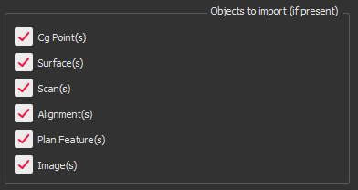
  • In these files, the following objects can be imported:

    • Cg Points (Coordinate geometry point)

    • Surfaces (including boundaries, breaklines, contours and data points)

    • Scans (clouds referenced in the xml file)

    • Alignments

    • Plan Features

    • Images

  • You can choose what to import by checking the options

images/download/attachments/113546377/image2019-7-1_16-13-16.png

.igs
.iges

.stp
.step

  • Reads objects from an IGES file or STEP files

.ifc
.ifczip

  • Reads objects from an IFC file (IFC 2x3)

See Import BIM Project.

.rvt

  • Reads objects from a Revit file (from 2015 to 2020)

Reference points

Currently, the Project Base Point, Survey Point and Internal Origin aren't read.
All data are imported considering the Project Base Point to be the origin of the WCS.

See Import BIM Project.

.p4d

  • Reads an image from a Pix4D Project file

  • The image and the .txt and .cam files have to be in a sub-directory of the one containing the .p4d file

.out

  • Reads images from a Bundler Project file

  • The images have to be in a sub-directory of the one containing the .out file

.jpg
.jpeg
.bmp
.png
.tif
.gif

  • Reads an image from an image file

  • If there is no side files (in the same folder), the image type will be unknown unless it is an ortho-image with embedded world file.

  • If there is an INCAM file, the image will be set to perspective type with known internal parameters.

  • If there is an EXCAM file, the image will be set to perspective type with known external parameters.

  • If there is a JGW, BPW, PGW or TFW file, the image will be set to ortho-image type with known external parameters.

Import of clouds

  • Number of points to import:
    For most of the file formats containing clouds, you can reduce the number of points in each cloud during import.
    The default value is 6 million points. The maximum value depends on your hardware configuration. For instance, a 64 bit mode computer with 8GB RAM can process about 200 millions of points.
    The reduction process removes the points according to a constant density: points are removed where the density is high and where there is not a lot of change in the surface. Display is resized to show all the imported points (with a default maximum of 1 million of points, see the Cloud settings page).
    Manipulating very large clouds can lead to memory saturation or computation problems. To guaranty a smooth experience and ensure stability during any processing, a default reduction to 1 billion points is applied on each imported cloud.

  • Scanning direction:
    For some formats, the software can load the scanning direction (direction from which each point is scanned). Some formats store the scanning direction, but this is not the case for all of them.
    The scanning direction is mainly useful for thin parts, for instance, it is used in the following commands:

    • Cloud display in a special representation mode named Smooth with back in reversed color: the scanning direction allows to distinguish the back and the front of the cloud (only for representation purpose - in a similar way to the mesh display)

    • In the Best Fit Registration command, clouds for which scanning direction is known can be attracted by nominal data (CAD or mesh) with a valid orientation. This is mostly important for thin parts scanned from only one side (but with a nominal data containing the thickness)

    • In the Refine Mesh commands, clouds for which scanning direction is known can better adjust the mesh position in the middle of the noise thickness by detecting the different scanning layers. This is mostly useful for thin parts scanned from both sides

    • In the Separate Visible Points command, the scanning direction can be used to remove the points which were scanned in bad conditions (tangentially to the part)

Import of meshes

For most of the file formats containing meshes, if the file contains several meshes you can choose to group them all in a compound.

Import of polylines

If more than one polyline is imported the software creates a set with all the polylines that you can explode if you need to retrieve all of the individual polylines.