Best Fit Registration
![]()
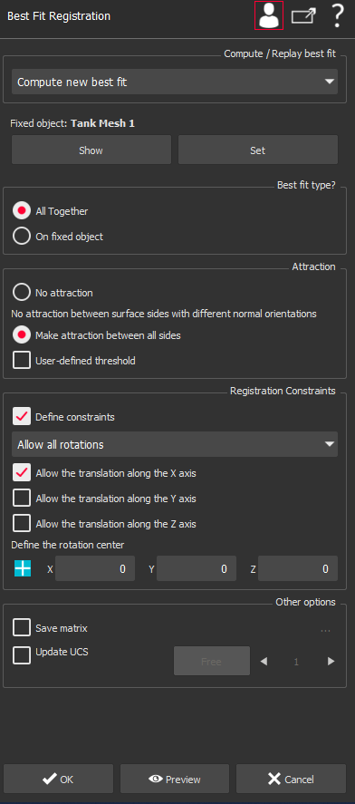
This command analyses the overlap of selected objects to calculate the best fit of these objects. Best fit means the transformation that minimizes the distance with other objects in a least squares sense. This function assumes that the first object in the selection is the reference immobile object, unless you want to replay the previous best fit operation. With this command you can:
All together: best fit of all objects together. This means that if N objects are selected, the best fit of each object is computed with the other N-1 objects. This option is very useful in case of many overlapping point clouds covering a closed shape. If N=2, there is no difference with the next option.
On fixed object: the best fit of all objects onto the fixed object of selection. This means that objects 2 to N are all best fit to object n°1.
Compensate ball radius on fixed surface or mesh: a ball radius compensation onto a surface or a mesh. This is designed to make registration of point clouds measured with mechanical probes onto theoretical model. This option is available only if the fixed object is a mesh or a surface. This option works as the previous option except that a compensation of the spherical probe is added.
It is also possible to replay the previous best fit (or to replay reverse previous best fit) with the selected objects. In this case, all the selected objects are moving together the same amount, including the first.
The command applies the following rules to decide whether an option is available or not:
Legal objects to compute a new best fit are restricted to meshes, surfaces, clouds, geometric features and/or polylines. If your selection contains at least one entity that is neither a mesh nor surface, cloud, voxel, geometric features or polyline, the option Compute new best fit will be automatically disabled and Replay option will be selected.
You need at least 2 objects to Compute new best fit. If there is only one object in the selection, the option Compute new best fit will be automatically disabled and Replay option will be selected.
To make a ball radius compensation, the fixed object must be a mesh, voxel or a surface. If this condition is not met, the option Compensate ball radius will be automatically disabled.
In some cases, the best fit can be applied without manual pre-positionning (Pre-align in a first step option available in advanced mode). The condition in which the automatic pre-positionning will work well is the case where the 2 objects that are to be best-fit together have a complete overlap. If this condition is not fulfilled, all the objects must be roughly pre-positioned so that overlapping zones are not ambiguous. If the objects are too far, you must, first, make the pre-positioning operation using the commands:
Insure that all objects are roughly pre-positioned or fit the conditions where the automatic pre-alignment will work. If not, use the above commands to pre-position.
If you want to compute a new best fit, select first the object that will remain immobile. Refer to the rules above (1, 2 and 3) for the authorized entity types. To obtain a good result, it is highly recommended that the immobile object covers the main part of your model. Press the CTRL key to add next objects to selection and select all the other mobile object(s) and launch the command. The command dialog box appears.
Note
If you have more than one object that must be used as reference immobile object, you must merge all these objects together to make a single object. You can do that using one of the commands Group Mesh or Merge Clouds, Extract Cloud. Remember that your original object remains accessible by restoring them from the recycle bin.
|
|
Warning Depending on the number and type of objects selected, some of the options can be disabled according to the rules above.
Information about transformation: Once the transformation(s) has been computed, the command gives you information about the movement of all the selected objects. In an attached dialog box, you can see a detailed listing of transformations applied to the different objects inside the selection, which define the combination of the 6 degrees of freedom:
Note The 3 rotations are also called "Euler angles". Here the angles are assumed to be applied in order Z->Y->X such that R = Rx.Ry.Rz, which is the most common convention. In addition, the command finds the point of the model having the greatest movement and tells you this distance, which is greater than all other points of the model. Update coordinate system n°: When connected to a laser arm, this option allows to create or update the coordinate system the arm will use for the next measurements (commands Measure through RDS, Probe Feature). Select the coordinate system number with the the arrow (up and down). You can define up to 9 coordinate systems. If a matrix already exists for the selected coordinate system, you can either:
Note The option Save matrix allows to save matrix result inside a file. Select the path and the name using the button '...' |
Practise
See the Exercise: Align a point cloud on a reference model according to the shape (Best Fit)
in the Beginners Guide.
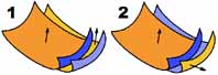
Use cases where the Pre-Align option can work or not
|
|
|
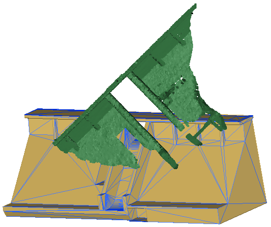
Typical example where the automatic pre-alignment will NOT work: the mesh contains the back of the dam whereas the cloud doesn't - the overlap between the mesh and the cloud is only partial. |
|
|
|
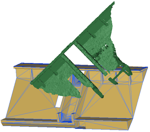
Typical example where the automatic pre-alignment will work: the mesh and the cloud only contain the front of the dam - the overlap is almost complete. |